There are currently four ways to get audio out of the RPi:
- Use the audio out 3.5mm jack. It’s very easy to get it to work, but the sound quality is pretty bad, since it uses PWM to generate the sound. Due to that, its real resolution is in the neighbourhood of 11 bits. We have no use for that.
- Use the HDMI port. It works OK, but is useless to us audiophiles.
- Use a USB to I2S adapter, such as an Amanero or an XMOS-based device. Now we’re talking. They work quite well, and the quality of the I2S signal is dependent largely on the technology used (CPLD vs. XMOS, etc) as well as the quality of the on-board clocks. The problem is that they add another link to the audio chain, as well as increase the cost. Remember, the RPi is supposed to be a low cost solution.
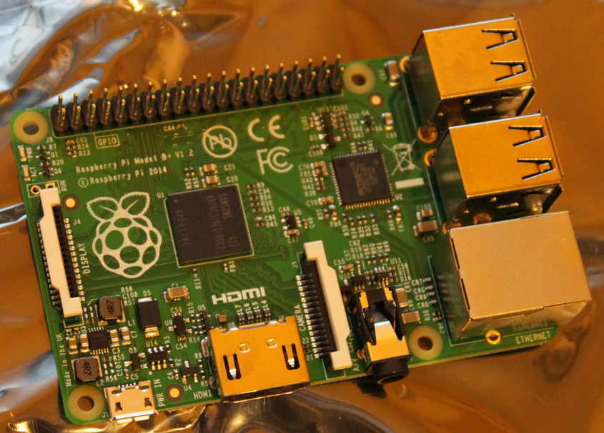
- Use the GPIO pins of the RPi to get direct I2S output. This sounds way more interesting, right? Let’s try that!
According to several sources on the Net, this is the pin out:
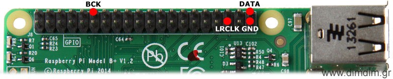
You will probably notice that the RPi does not support MCLK output. This means in practice that your DAC will need to have its own on-board clock (or internal PLL / oscillator or whatever). We can live with that.
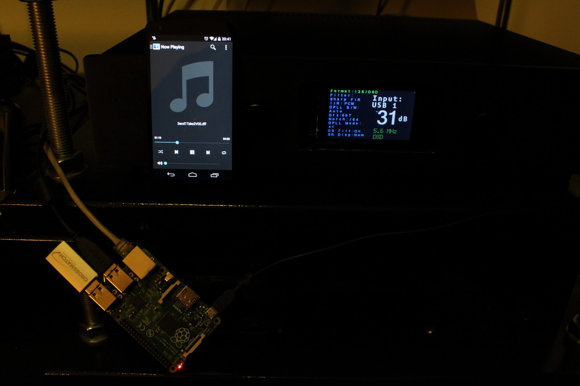
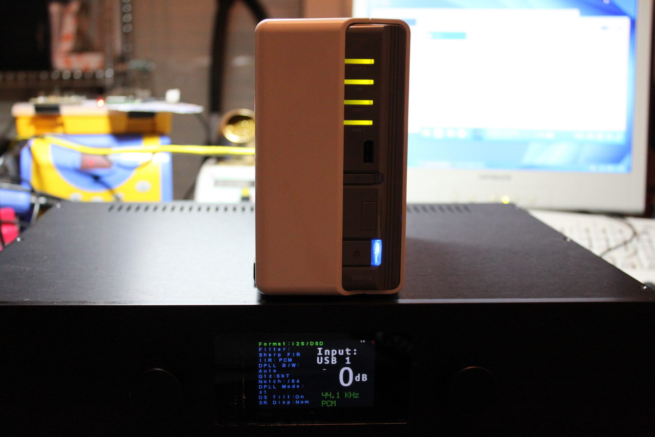
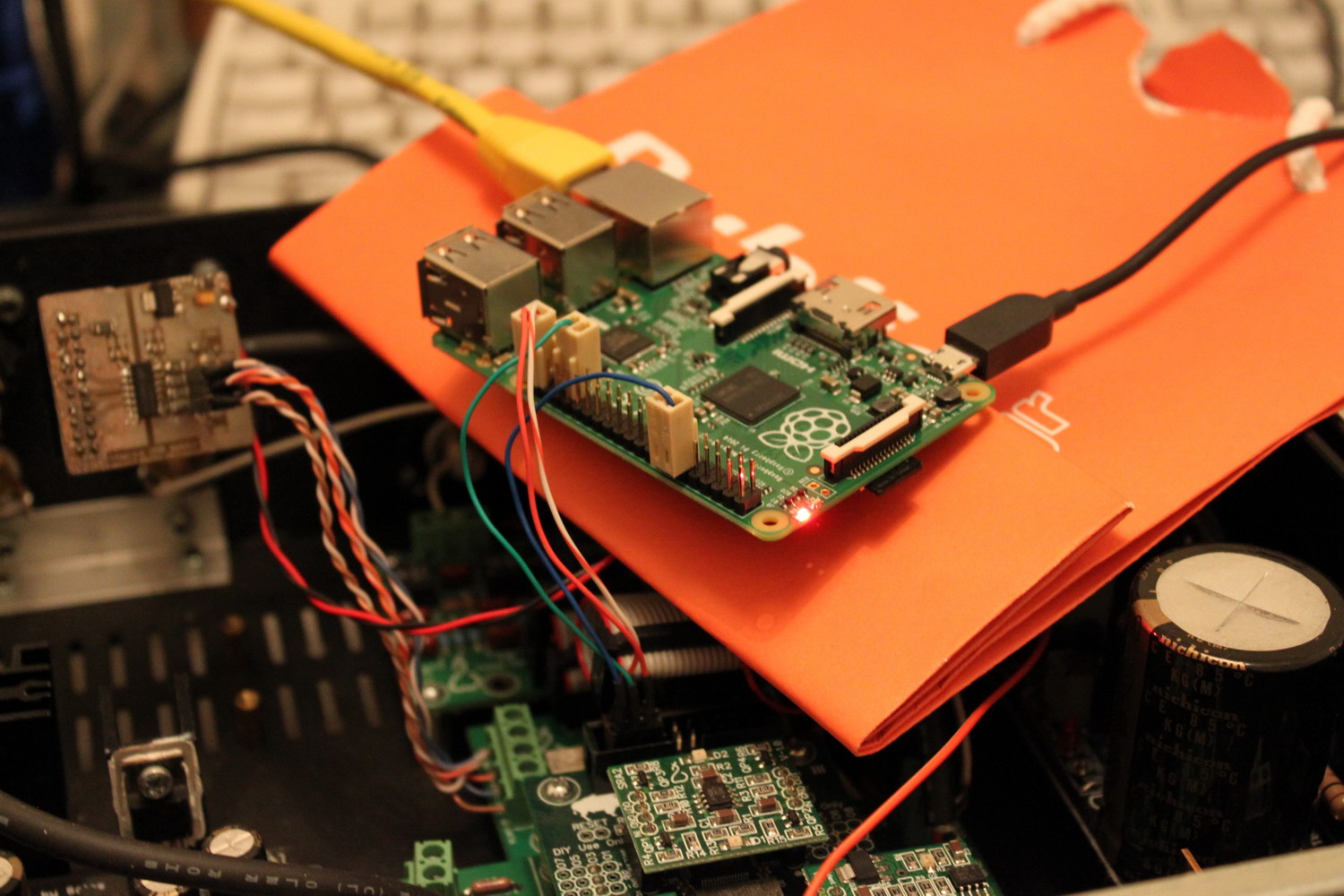
Luckily, my Buffalo III has its own clock (of course it does!) and thus can be connected quite easily. Let’s try that:
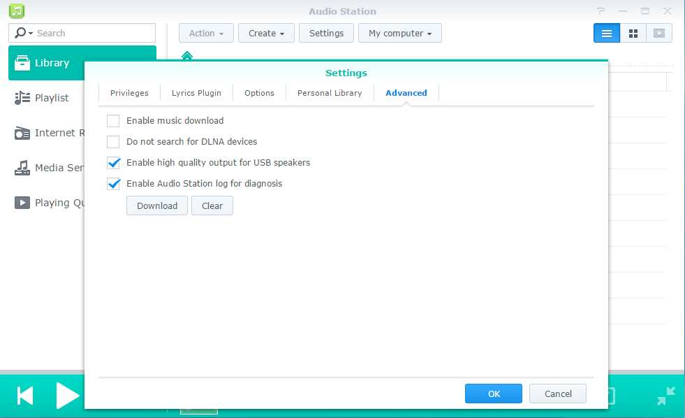
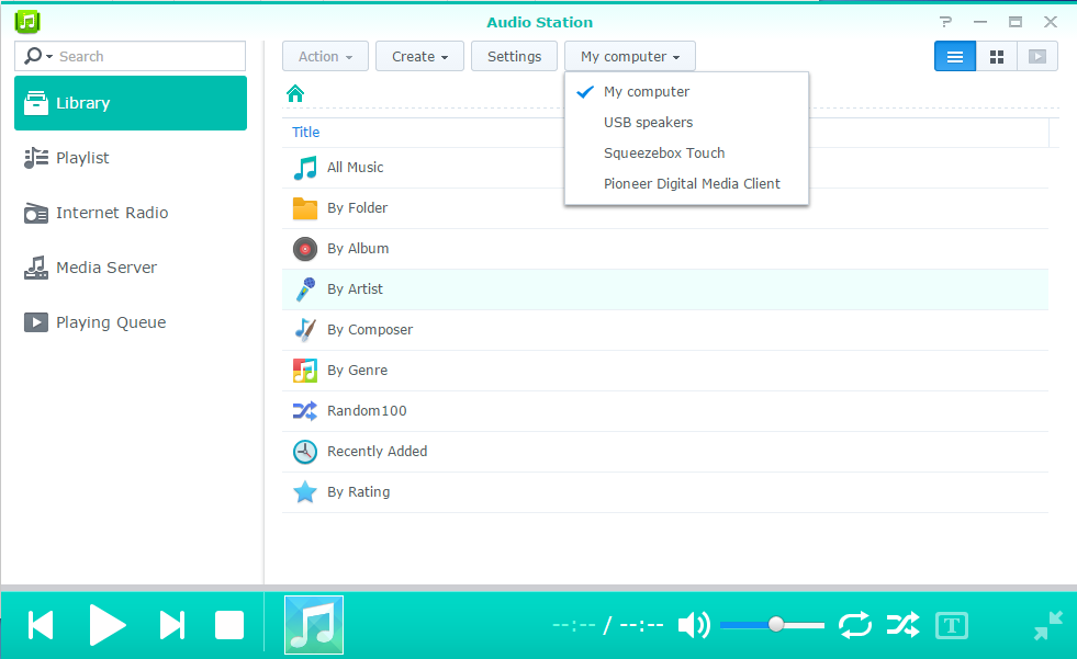
Now we have to configure the software for I2S output. For my distribution of choice, Archphile, it’s a piece of cake: http://archphile.org/howto/i2s-dacs-and-the-raspberry-pi/
Audio playback works just fine!
Well, almost fine..
You see, in theory the RPi has a bit of a problem with its I2S output. Since the only clock onboard the RPi is a 19.2MHz crystal, it should have trouble generating proper clocks for its I2S output. For example, for 44.1KHz audio, the LR Clock must be running at precisely 44.1KHz. That is not possible, since the frequency is not a multiple of 19.2MHz. Thus, the frequency can be either 19.200.000 / 435 = 44.138KHz or 19.200.000 / 436 = 44.0366KHz. This is a limitation of the Broadcom BCM2835 in conjunction with the 19.2MHz crystal and there is nothing that can be done.
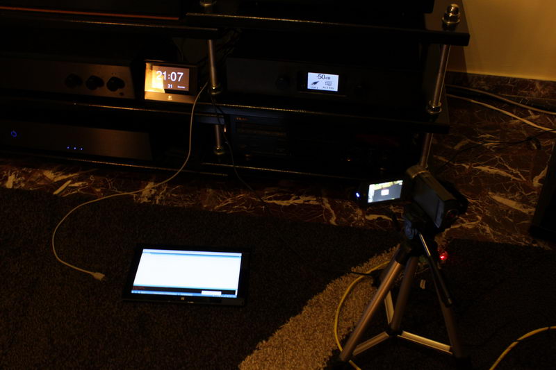
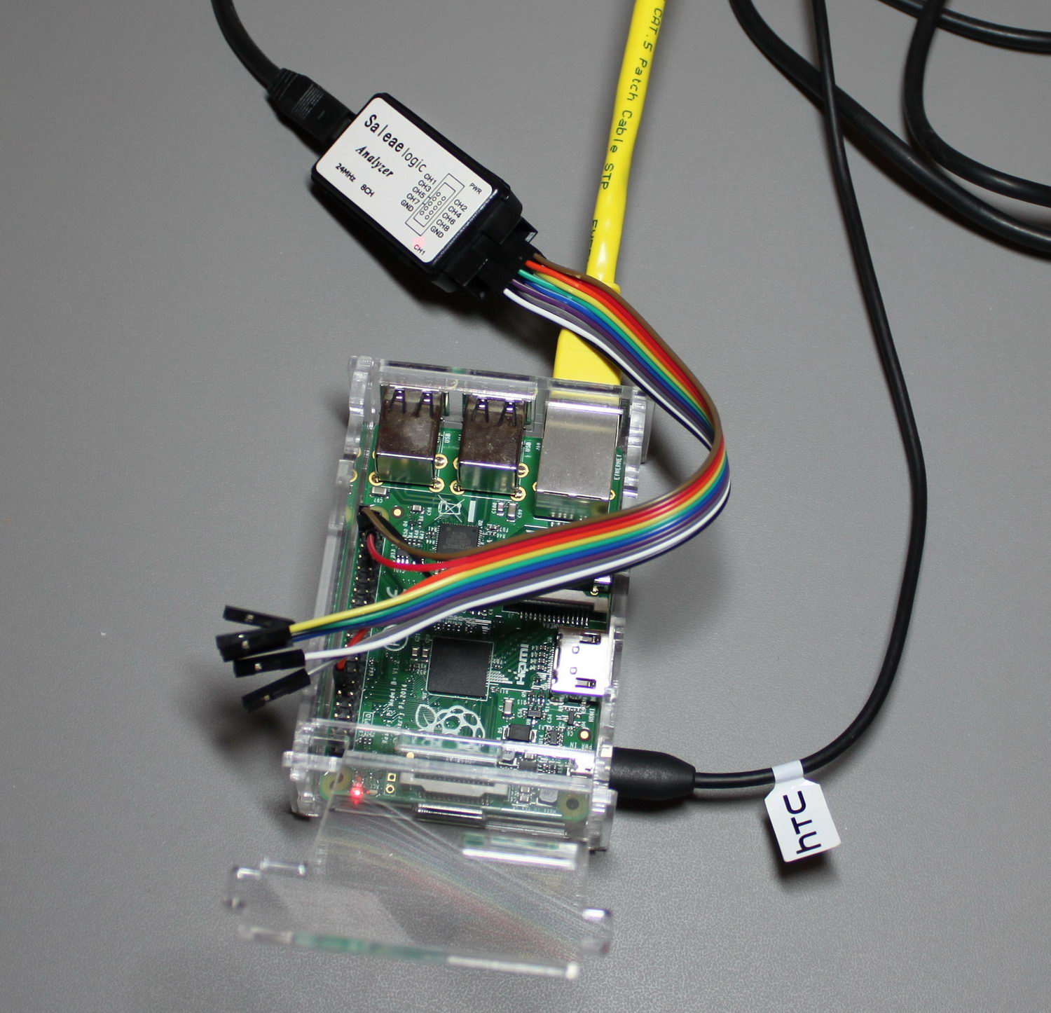
In order to confirm the theory, I decided to run a few tests. I hooked up my logic analyzer to my RPi, set it up for I2S output, and fed it some 44.1KHz music.
I took 1 sec worth of samples with my logic analyzer, configuring it for I2S signal. I got this:
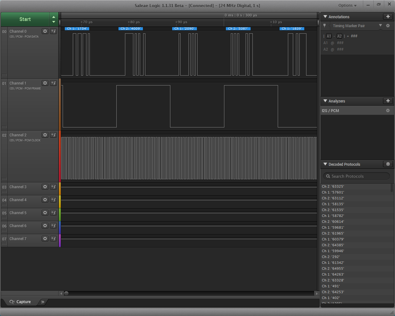
The PCM Clock is already appearing a little dodgy. Let’s zoom in:
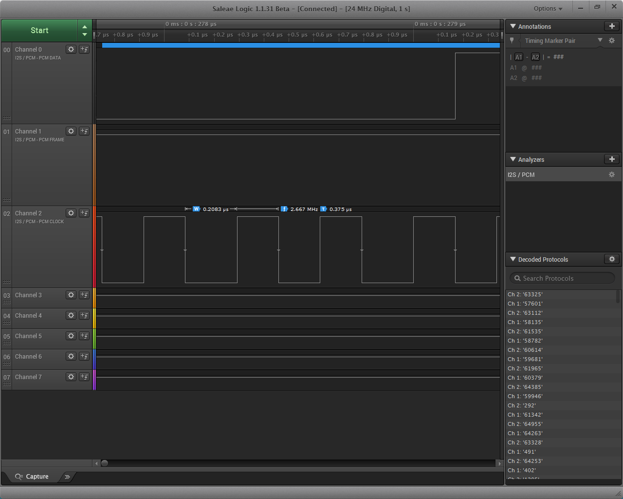
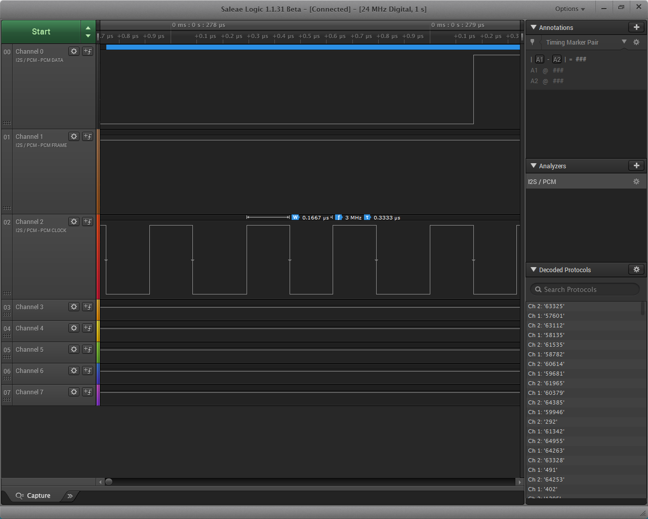
As you can see, the pulses do not have the same duration. They appear to alternate between two values. So it is obvious that the signal has jitter. A lot of jitter. Since we’re here, let’s have a look at the LR Clock signal as well:
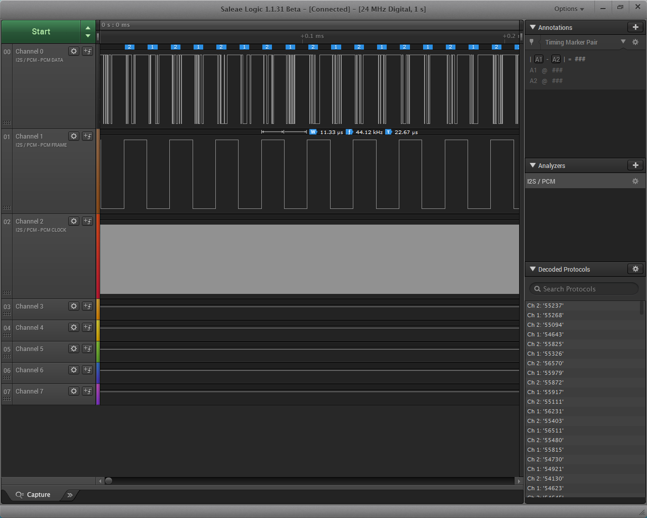
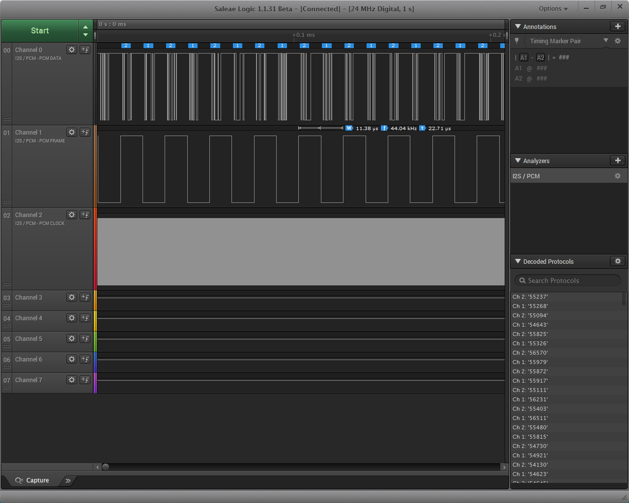
The duration of the pulses appears to alternate between 11.33μS and 11.38μS, giving respectively 44.12KHz and 44.04KHz, values very close to the ones I calculated previously.
So, the theory is sound and the RPi’s clock is not up to snuff by strict standards. What this means is that the RPi’s I2S output is not capable of “Hi End” audio transmission. It is essentially not bit perfect (edit: this is not correct, strictly speaking. It is in fact bit perfect, it is just not “proper”.).
In the real world, chances are that this problematic clocking will not be particularly audible under normal circumstances, say with a normal-specc’ed sound system. But an audiophile should definitely steer clear of the RPi’s I2S output, instead opting for a USB to I2S interface.