Arduino controlled Dual Mono AK4490 DAC (Part 2)

Following up on Part 1, it’s time to talk about the “brains of the operation”. Bare with me, this is going to be a rather long read.Hardware selection
The DAC needed to be controlled by a microcontroller so I looked into my options. I wanted something that would:

  • Be easy to program, so the Arduino IDE was a must.
  • Be able to drive a TFT.
  • Have enough storage capacity to store enough code & fonts for the TFT.
  • Be readily available.
  • Be relatively low cost, since it would have no influence on the dac’s SQ.
  • Be easy to build / integrate into a new design, even by a novice.

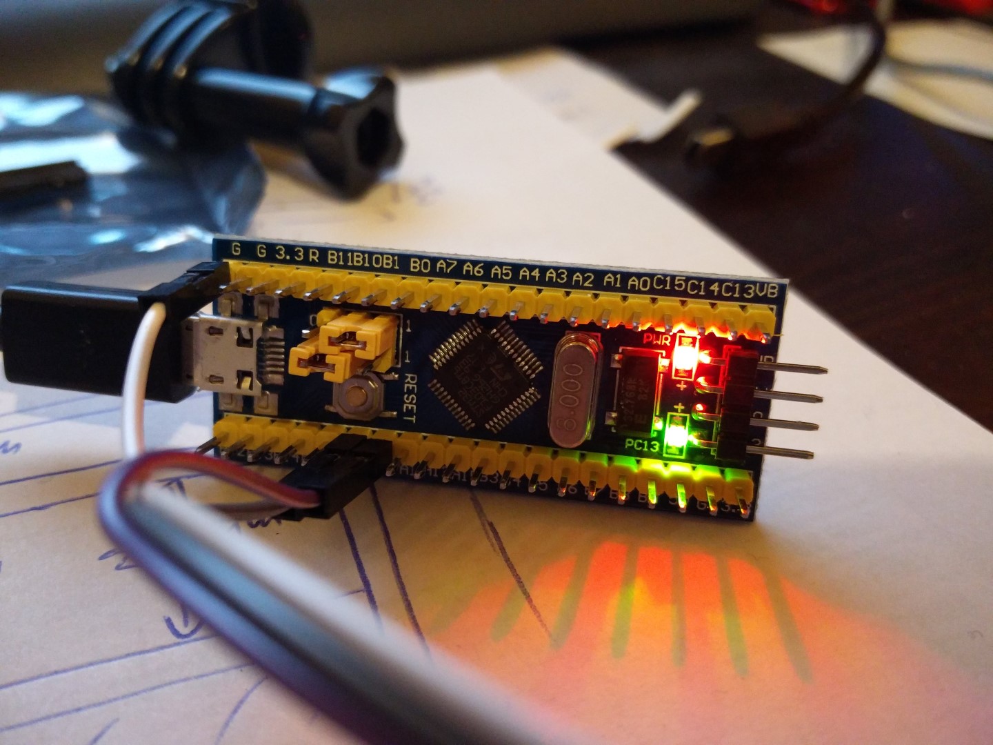
After some consideration, I decided to use an STM32F103 ready-made module. It would plug in to a “mainboard” of my design, along with the chosen TFT. It would be fast enough, have enough flash & ram, be easy to integrate and develop for and it would cost next to nothing.

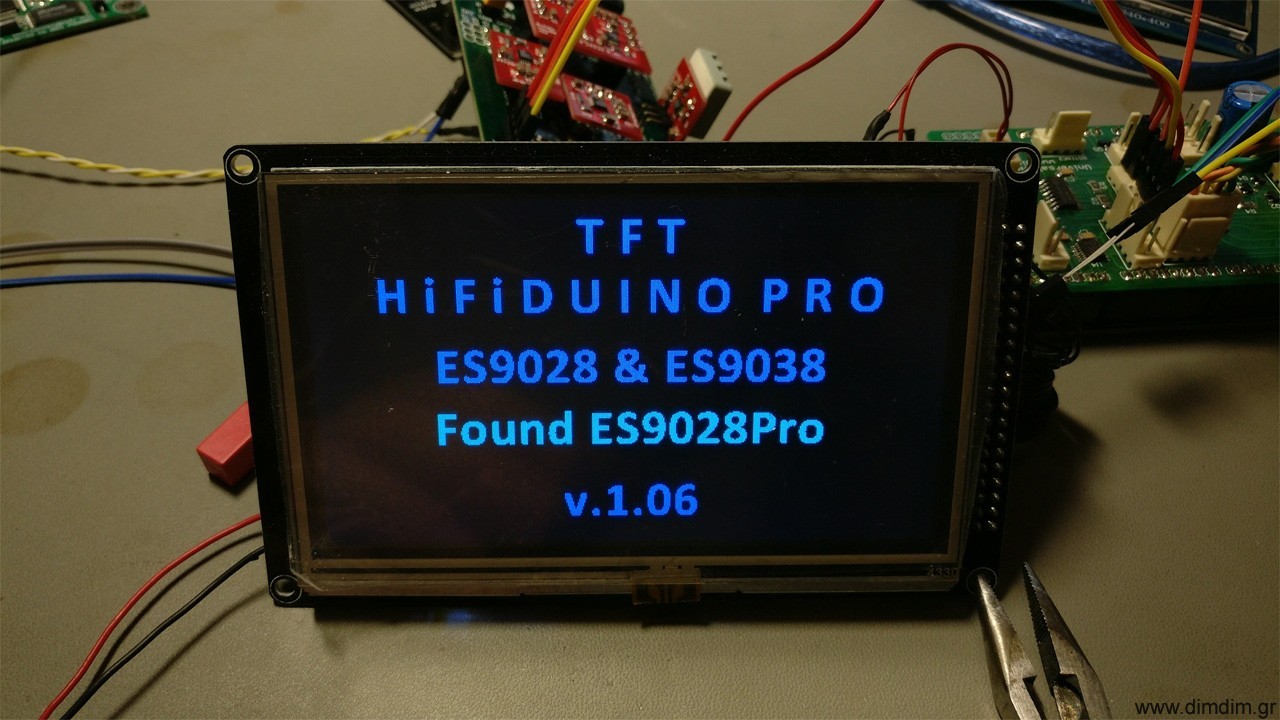
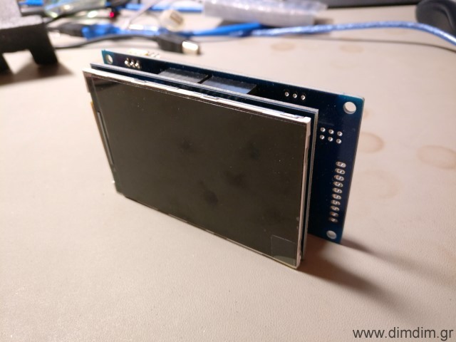
Next up was the TFT. I’d seen on Ebay an interesting one that was relatively big, high resolution and inexpensive. It was this one:

It can be found on Ebay by searching for “3.5 tft uno 320 x 480”. Expect to pay 6-8€ inc. shipping.

After some searching I found a suitable library that (after some slight tinkering) would allow my tiny STM32 to drive it properly. (Note: do not download the library from this link. I will provide a customized version of the library together with my code).

I found a ready-made library for configuring the Si570 and modified it to run on my STM32, using one of its hardware I2C ports. I will also include this library in my code. To complete the recipe I also found working rotary encoder and IR receiver libraries.

The code

Next up was the prototyping work. I adapted my TFT HiFiDuino Pro code to run on the STM32 & TFT combo, with support for AK4490 dual mono operation. The end result had this feature list:

  • Support for either Dual Mono or single chip setups.
  • Support for the Amanero Combo384 USB to I2S module (must be set up as slave with MCLK/2 and F0,1,2,3 enabled).
  • Control with one rotary encoder with push-to-select functionality.
  • IR Remote support.
  • Support for software volume control, from -99dB to 0dB
  • Display incoming signal sampling rate and type, determined by “reading” the relevant I/O pins of the USB to I2S board.
  • Display and control of the AK4490’s digital filter.
  • Selection of the proper MCLK frequency according to incoming SR and type and programming of the Si570 accordingly.
  • Control of “DSD Direct” function of the AK4490s.
  • Control of the DSD Filter’s Frequency (50KHz or 150KHz).
  • Control of the Sound Mode of the AK4490.
  • Choice of either inverted or normal analog output for the AK4490s.
  • Choice of two sets of MCLK frequencies, either 22/24MHz or 45/49MHz.
  • Remote power on/off functionality (or always on – configurable in the code).

Software Requirements:

In the download I am including the modified versions of the libraries (as mentioned above) as well as the necessary font files. Be sure to extract the contents of “Libraries (place in Libraries folder)” to your Arduino IDE’s “libraries” folder.

Download it here: aKduino v2 (83375 downloads )

Here is the revision history:

v1.72 24/12/2017:

  • Minor changes to make compatible with current stm32duino core (changed HardWire.h to Wire.h and other minor stuff).
  • First public release as part of completed dual mono DAC project.

v1.66 10/10/2017:

  • Minor volume bugfix.
  • SuperSlow filter still problematic.
  • Enabled DAC synchronization feature (experimental..).

v1.64 30/09/2017:

  • Bugfixes.

v1.60 20/09/2017:

  • Added support of rotary encoder and IR remote control.
  • 3.5″ TFT support.

v1.50 07/01/2017:

  • Added support of rotary encoder for volume control.
  • Bugfixes related to DSD.

v1.41 06/01/2017:

  • Added support for dual mono mode.

v1.36 03/01/2017:

  • Added very basic TFT support.

v1.35 20/12/2016:

  • Code cleanup for first public release.

v1.33 19/12/2016:

  • Added full control of sound parameters through serial port.

v1.27 18/12/2016:

  • First functional version.
  • Automatic switching between PCM and DSD by monitoring DSDPIN.

The “motherboard”

After I was certain that everything related to the software was working the way it should, I designed a “motherboard” that would take care of the following:

  • Accept the STM32F106 board.
  • Accept the 3.5″ TFT.
  • Accommodate an 24LC256 EEPROM chip, used to store the DAC’s configurable settings.
  • Accommodate two sets of I2C signal isolators and I/O expanders.
  • Include headers for the encoder, IR receiver, power relay, non-isolated and isolated I2C communication, unused uC pins, etc.

This is what I ended up with:

Basic Hardware Requirements:

  • STM32F106 module (a.k.a. “blue pill”, search Ebay for “stm32f106c8t6 board”)
  • 3.5″ TFT with resolution of 320 x 480 (Search Ebay for “3.5 tft uno 320 x 480”)
  • 24LC256 EEPROM chip
  • I2C Isolator ICs, I/O expanders, passive components, etc (see BoM)
  • Rotary Encoder
  • IR Receiver
  • Compatible IR remote control (Apple Remote or other – in any case you must edit the code and input the proper IR codes for your remote, see below)
[table “” not found /]

How do I make it work?

Power

You have to supply the board with 5VDC at ~300mA through header DC_5V.
[table “” not found /]

Basic connectivity

Serial port:
[table “” not found /]

Rotary encoder:
[table “” not found /]

IR control:
[table “” not found /]

If you will be controlling a power on/off relay, you can use the POWER_RELAY header:
[table “” not found /]

Expansion header:
[table “” not found /]

I2C header (non-isolated):
[table “” not found /]

Isolated I2C ports

The board has provisions for two separately isolated I2C ports, complete with I/O expanders on their isolated sides. The idea is to connect the DAC board to one of the isolated ports (I2C_ISOL1 & MCP_ISOL1) and your USB-to-I2S board to the other isolated port (usually MCP_ISOL2)
[table “” not found /]

[table “” not found /]
[table “” not found /]
[table “” not found /]

That’s it for Part 2. Stay tuned for Part 3: The output stage.

Arduino controlled Dual Mono AK4490 DAC (Part 1)

For the better part of a year I’ve been busy developing what one would call a “respectable” DAC from scratch. It has been a team effort, with different people becoming more involved with specific aspects of the project, but pretty much everyone involved ended up learning a lot about DACs. Right now, the project is for the most part finished, in that it is fully functional with a USB input and a pair of single ended outputs (or balanced, if you use a passive transformer-based stage). It is controlled by an Arduino-compatible micro-controller, running my aKduino v2 code (more on that in a future post).

I will do a series of posts detailing the design and build process, with each post covering a specific PCB. When the series is complete, the contents of all of the posts will be concatenated into a project page.

So, without further ado, this is the schematic of the main DAC board:

(Right click, Save Image As.. to download it in full resolution)

This is the 4-layer PCB:

This is the parts placement diagram:

And this is the BoM (v1.9) in xls format: Dual AK4490 DAC (main board BoM) (13795 downloads )

Design considerations

The design goal was to do a dual mono design so as to maximize SNR and channel separation. A 4-layer PCB design was chosen so as to have a very solid, low impedance ground plane as well as proper power and signal planes. The I2S, audio signals and power after the local LDO regulators are routed on the top layer, the 2 middle layers are ground and power planes, and the bottom layer serves to route I2C signals and some power lines.

Power

All of the local power supplies are implemented using the currently top-of-the-line LT3042 LDOs. The VDDL & VDDR (analog power supplies) are set to 7.2V so as to maximize SNR and dynamic range. There is provision for providing separate pre-reg power supplies for the L and R channels (headers AVDDL and AVDDR) but I don’t consider that to be critical to SQ since there are local LDOs and the power draw is very very small. In my implementation I’m using a common pre-reg for both the AVDDL & AVDDR. The AVDDs and DVDDs are also supplied by LT3042 LDOs set to output 3.3V. The Si570 has its own dedicated 3.3V supply implemented with an LT3042 and features extra filtering.

Overall, the power requirements of the board are:
1) AVDDL: 8-10V DC at 40mA max
2) AVDDR: 8-10V DC at 40mA max
3) DVDD: 4-6V DC at 200mA max

Clocking & input signals

It was decided that the MCLK would be provided by a programmable low jitter oscillator, namely the Si570. This way we could select different MCLK frequencies at will, supporting different sampling rate families and different USB to I2S boards.

Speaking of USB to I2S boards, the DAC board has a very specific requirement: The USB board must be able to receive MCLK externally. In other words, the DAC board and USB board must be clocked from the same oscillator. This is due to the AK4490’s design. Unlike the ESS designs which by default run asynchronously, it needs to be on the same clock domain as its I2S sources.

So, the DAC board needs to output MCLK back to the USB board. There exist a number of USB boards that support that. The most popular ones are the Amanero Combo384 and JLsounds’ I2SoverUSB.

Since I had decided to do reclocking using flip-flops as close to the AK4490s as possible, and the flip-flops are clocked by the MCLK, its frequency needs to be sufficiently high in order to reclock signals corresponding to high sample rates. This translates to 49.152 MHz for sampling rates of 384KHz. If you’re content with going only up to 192KHz, you can use a MCLK of “just” 24.576 MHz. Of course you will also need the corresponding MCLKs of 45.1584 and 22.5792 MHz for the 44.1K families of SRs.

If you decide that you don’t want to do reclocking on the DAC board, you can just not solder on the flip-flops and just connect the proper pads together with some wire so as to bypass them. That way you can run with 22.5792 & 24.576 MHz clocks with SRs up to 384KHz (and probably beyond..).

If you decide that you would also prefer to not use the Si570 and just clock the DAC board directly from your USB to I2S board (or other suitable I2S source) you can also do that. You just don’t solder-on the Si570 and make a couple of changes to the Arduino code (to be implemented..).

But I urge you to try the Si570 & reclocking way first..

Construction hints

Start by first soldering on the power supply components (LDOs, resistors, caps, etc.) and testing that everything works the way that it should.

The LT3042s are pretty tiny and its easy to make a mistake while soldering them. I’ve found that the easiest method is by using a hot air rework station. First I use a regular soldering iron to tin the thermal pad and the pads with a small amount of solder. Then I apply a good amount of high quality solder paste, put the LDO on top of the pads and heat the area of the board until the solder melts. I set my hot air station to a relatively low temp of ~280 degrees C and the process takes less than a minute (per LDO). But you could also solder them with a soldering iron. To solder the heatpad, warm up the pad from the underside of the board and add solder.

After the power section, you should solder on the AK4490s and other low profile components. I do that with a low power (18W) soldering iron with a fine tip.

Next up is the Si570 programmable oscillator. I start by putting a little solder on one of the pads:

Then I add soldering paste and I place the Si570 on top of the pads. I use the fine tipped soldering iron to melt the solder on the tinned pad, effectively soldering the Si570 on the board. I then proceed to solder the rest of the pads by applying heat with the soldering iron to the side of the pads of the Si570 and adding solder.

You should finish up by soldering the electrolytic capacitors and other higher profile parts.
Beware that the spacing around the electrolytics is very tight. You should take that into account when selecting parts. The parts in the BoM are sure to fit in the available space.

That’s it for Part 1. Stay tuned for Part 2: The Controller.

ArDAM Lite custom PCBs for diyaudio.com

This post serves mainly as a placeholder for the build guide that I wrote for the PCBs, since it seems that some people had problems with the download link that I provided.

The build guide can be downloaded by clicking here: ArDAM Lite Build Guide (69874 downloads )

I do have a few left over PCBs, if you’re interested contact me for more info.

STM32 Microcontrollers & Arduino

I love Arduinos as much as the next (nerdy) guy, but let’s face it, they are no powerhouses (DUE and ZERO excluded, but they discontinued the former.. go figure..).

The Atmel AVR series is 8-bit and its clock is ridiculously slow by today’s standards.

Sure, you can get it to do some things with impressive speed if you are willing to do some low-level programming but I myself do this as a hobby and thus don’t really want to deal with assembly-level code.

If only there was a fast and cheap microcontroller that was easy to program..

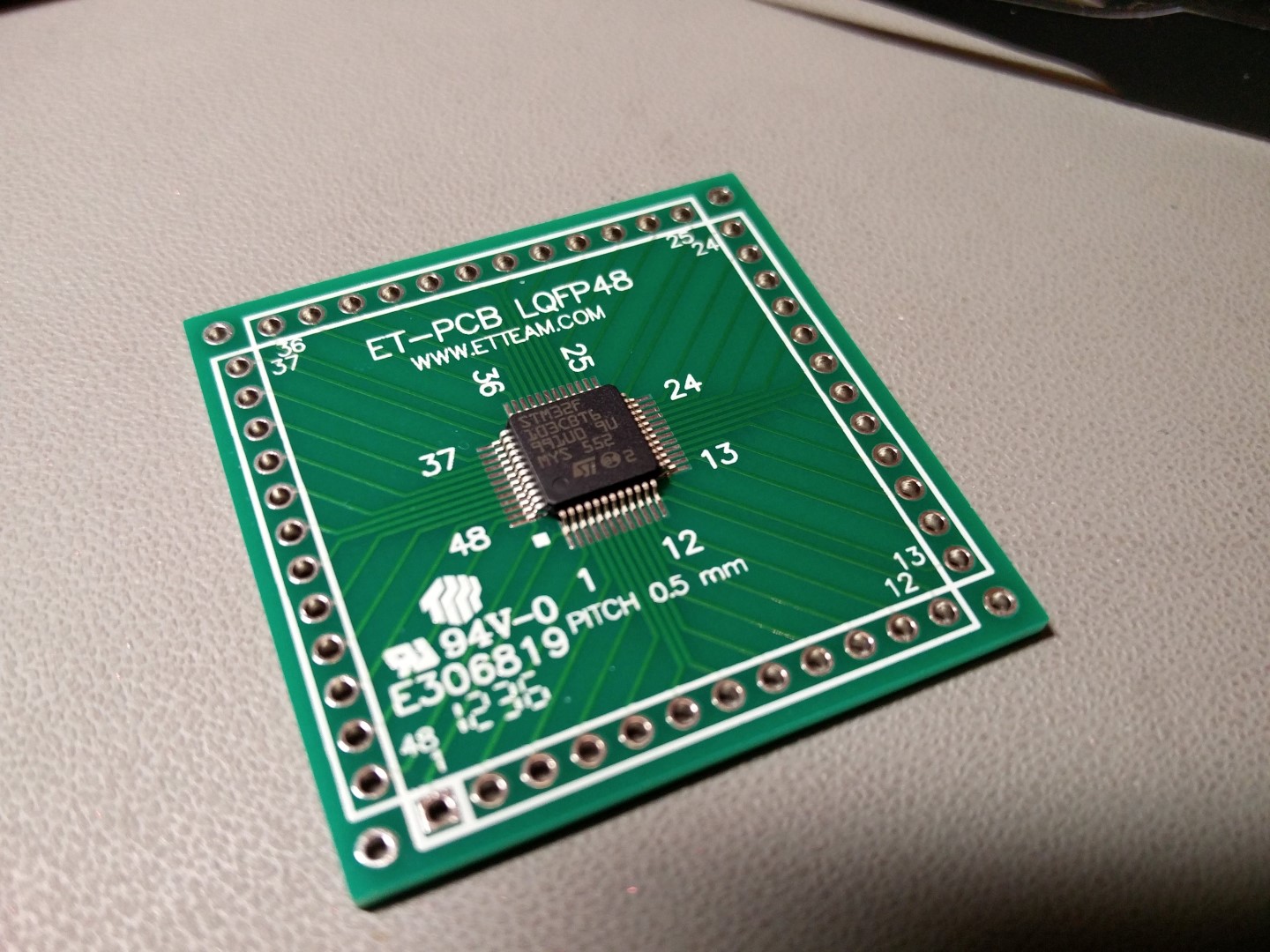
Enter the ST STM32F103C family of microcontrollers.

These little wonders are:

  • Friggin’ fast. 32bit ARM architecture running at 72MHz.
  • Very well equipped in the I/O department.. 2 x UARTs, 2 x SPI busses, 2 x I2C ports, etc.
  • Easy to program using the familiar Arduino IDE, thanks to the work done by the wonderful people at www.stm32duino.com
  • Dirt cheap. You can get an Arduino Nano – sized board for less than 3€ shipped.

It’s pretty easy to get started using these microcontrollers. All you have to do is buy a tiny board from Ebay. You will also need a USB to Serial adapter that works with 3.3V voltage levels (you probably already have one of those lying around already..).

These tiny boards are known as “Blue Pills” or “Red Pills”, according to the colour of the PCB. There are other variations as well, but the red and blue variants are the most commonplace. They have relatively minor differences.

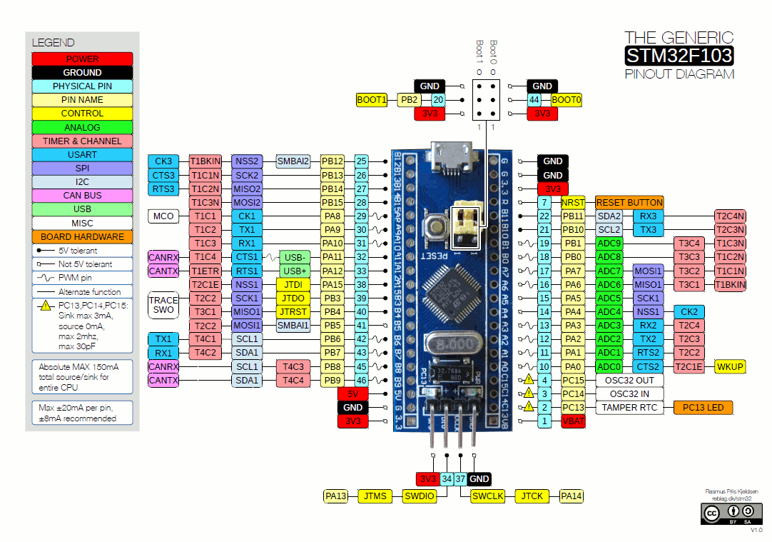
This is the pinout for either one of them:

To get started, you have to connect your USB to serial port adapter to the STM32’s RX1, TX1 and GND pins. RX from USB adapter goes to TX1 (PA9 pin) and TX goes to RX1 (PA10 pin).

To make the Arduino IDE compatible with these boards, you have to download the necessary files from here: https://github.com/rogerclarkmelbourne/Arduino_STM32

You then unzip the libary to C:\users\\Documents\Arduino\hardware\ or C:\Program Files (x86)\Arduino\hardware\

At the time of this posting, IDE 1.8.0 (latest available edition) is properly supported. You will also need to install support for the Arduino DUE or ZERO from the Boards Manager, otherwise you will get a “/bin/arm-none-eabi-g++: no such file or directory” error.

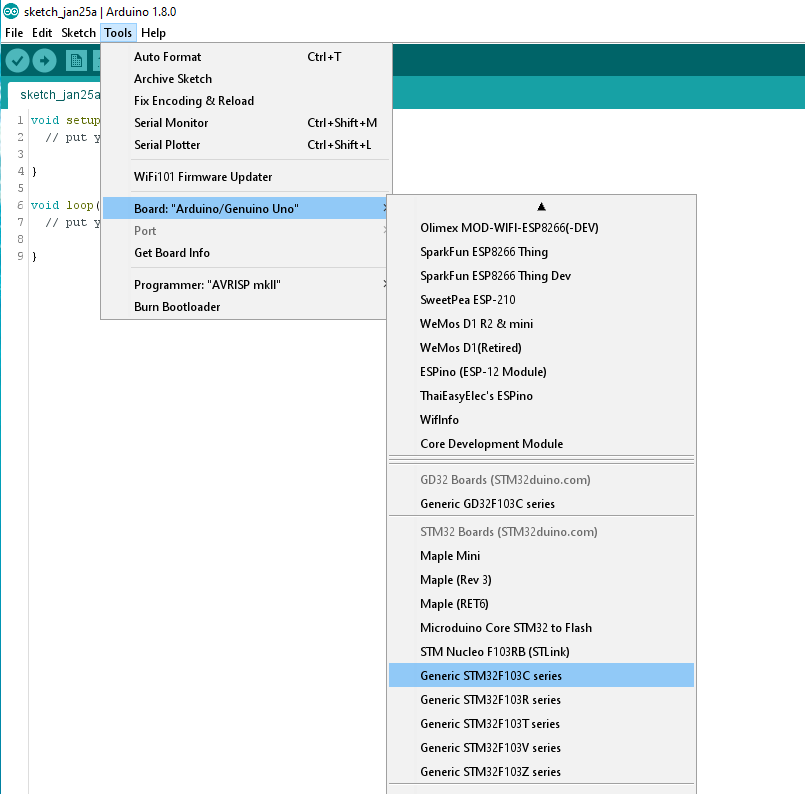
If everything went fine, you should see in your IDE a number of new available boards:

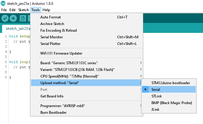
You select “Generic STM32F103C series”, the 128k variant, 72MHz speed, and Serial upload method:

You are now ready to try your first code upload.

The classic test is the Blink sketch:


// the setup function runs once when you press reset or power the board
void setup() {
// initialize digital pin PC13 as an output.
pinMode(PC13, OUTPUT);
}

// the loop function runs over and over again forever
void loop() {
digitalWrite(PC13, HIGH); // turn the LED on (HIGH is the voltage level)
delay(1000); // wait for a second
digitalWrite(PC13, LOW); // turn the LED off by making the voltage LOW
delay(1000); // wait for a second
}

In case of the STM32 uCs, the only necessary modification is changing the pin number of the LED to one compatible with the Blue (or Red) Pill (PC13).

Pin numbers for this family of uCs are not just numbers like they are for the Arduino boards (like 1,2,3….,A1,A2,…) but are named as they are described in the uC’s datasheet (PC13, PC14, etc.).

The procedure for uploading code is a little different than the one for the Arduinos. The STM32s come with 2 built-in bootloaders. One of them boots from system memory and the other from program memory. These different bootloaders are selected by changing the position of the BOOT0 jumper. You set it to 1 to boot from system memory or to 0 to boot from program memory.

To upload our code, we do the following:

  1. Set ‘BOOT0‘ to 1. This way we will boot from system memory which contains a UART to flash uploader.
  2. Press the RESET button.
  3. In the Arduino IDE, choose ‘Upload‘. On the board, the blue LED will start to flash.

After the upload is completed, our sketch will start. We should see the blinking LED.

If we want our uploaded sketch to boot automatically after the next power-on/reset, we need to set ‘BOOT0‘ back to 0 (so that on next powerup we will boot from program memory).

That’s pretty much it. Your next step should be to go to STM32duino’s forum and check out the libraries that have already been ported to the STM32duino environment.

Troubleshooting

If your sketch fails to compile, giving you a “/bin/arm-none-eabi-g++: no such file or directory” error, make sure that you have installed support for the Arduino DUE or ZERO from the Boards Manager.

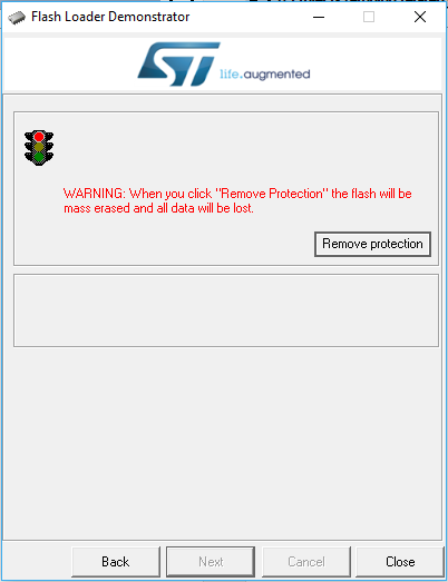
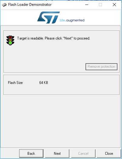
If you get an error on the IDE that it “Failed to erase memory”, that means that your STM32 chip is locked. No worries, all you have to do is go here and get ST’s Flash Loader Demonstrator utility. It will unlock the chip with minimum effort. Be sure to run it as Administrator in Windows.

st_flash_loader_demonstrator_1

st_flash_loader_demonstrator_2

Blue Pill reference: http://wiki.stm32duino.com/index.php?title=Blue_Pill

Controlling an AK4490 DAC with an Arduino

These days I’m co-developing an AK4490 based DAC. The aim is to end up with a no-compromise dual mono design, one that would perform at the very least on par with my Buffalo III.

Of course, to do that one has to run the 4490s in software mode.

As a matter of fact, it is generally preferred to run a 4490 in software versus hardware mode, for several reasons.

To begin with, in software mode the 4490 supports DSD decoding. It goes as far as to support a “Volume Bypass” feature which bypasses most of the processing done on the DSD signal (a.k.a. “the ΔΣ modulator”), resulting in more pure sound. But of course we do lose the ability to do volume control in software.

Software mode also allows us to try out all of the supported SQ features, like the different “Sound Setting” modes.

At last but not least, we get digital hardware volume control.

This is the prototype that we designed, getting I2S input from an Amanero and being controlled by my custom STM32 controller (more on that in the near future).

I searched the Net for any ready-made code that would control the 4490, but I couldn’t find anything worthwhile, so I began virtually from scratch.

So, my Arduino code (a.k.a. “aKduino”) enables:

  • Controlling an AK4490 through the I2C bus.
  • Automatic switching between PCM and DSD. It does rely on getting a “DSD type signal” from our USB-to-I2S interface of choice. The 4490 by itself is not capable of determining whether its input is PCM or DSD.
  • Setting the volume (in 9 steps.. just to confirm that volume control does indeed work).
  • Selecting “Volume Bypass” for direct DSD processing.
  • Selecting the internal DSD filter’s cutoff frequency (50KHz or 150KHz).
  • Selecting one of the 4 available PCM filters.
  • Enabling or disabling the Super Slow filter.
  • Selecting one of the 3 available “Sound Quality” settings.
  • Displaying all of the registers’ settings (for troubleshooting purposes).

Software Requirements:

  • Nothing (for now)

Basic Hardware Requirements:

  • Any Arduino (*)

(*) I should note here that the AK4490’s datasheet states that all of its I/O pins are expecting 3.3V logic levels but there has been a large number of reported cases of 5V Arduinos working without problems. I’m too much of a coward to try that myself so I used level converters for my initial testing and eventually a custom STM32 board that uses 3.3V logic but you may want to try your luck with 5V logic levels. Just don’t blame me if your 4490 gets damaged in the process.

Currently the code is at v1.35: aKduino Code (146693 downloads )

Here is the revision history:

v1.35 20/12/2016:

  • Code cleanup for first public release.

v1.33 19/12/2016:

  • Added full control of sound parameters through serial port.

v1.27 18/12/2016:

  • First functional version.
  • Automatic switching between PCM and DSD by monitoring DSDPIN.

Fixing startup issues with Arduino DUEs

If you’ve had a lot of Arduino DUEs go through your hands (or if you are just unlucky), chances are you’ve come across at least one that does not start-up properly.

The symptom is simple: you power up the Arduino but it doesn’t appear to “boot”. Your code simply doesn’t start running.

You might have noticed that resetting the board (by pressing the reset button) causes the board to start-up normally.

I had come across such a board a while back, and had thought to myself “cheap generic, probably faulty” and had just put it aside. At ~13€ it was no big loss.

A few days ago a fellow tinkerer (thank you Alex!) alerted me to a fix for this problem.

It appears that the problem was first spotted on Freetronics’ forum and was dealt with swiftly.

The problem occurs only on some DUE boards and is due to some undocumented behaviour of the ATSAM3X8E processor combined with the behaviour of some MOSFETS installed on the DUE boards. So its occurence is largely a matter of luck.

The fix is simple: you just solder a 10K resistor across the top of this mosfet:

DUE-Fix-culprit

This is a 10K 0805 resistor that is about to be soldered:

DUE-Fix-1

..and after soldering:

DUE-Fix-2

The discovery of the problem prompted a new revision of the reference design by the Arduino team.

This is what the Rev 2’s relevant part of the schematic looks like:

Arduino_DUE_Rev.2_sch

and the PCB:

Arduino_DUE_Rev.2

And this is what Rev 3 looks like:

Arduino_DUE_Rev.3_sch

Arduino_DUE_Rev.3

You will notice a new component, R99, plus the mosfet is now mounted vertically.

So, if you are shopping for a DUE, look for one with this mosfet mounted vertically, just to be on the safe side.

Universal Signal Isolator Shield: Rev. 1.2

Since there has been a lot of interest in my Isolator shield these past few months, I have been optimizing its design.

The result of this optimization is this PCB:
Rev.-1.2-pic
It’s called “the Rev. 1.2”.

Nothing major has changed. The pinouts are still the same, the major components are the same, the functionality is essentially the same.

The changes are as follows:

  • New SPI header. It just passes through the SPI signals, nothing more. It does not connect to anything on the board.
  • New SPI_CS header. Useful only if / when connecting SPI peripherals.
  • Reset button. Because you never know..
  • New circuitry for the POWER_RELAY header. It now uses a MOSFET and it includes a diode for the reverse current coming back from the relay’s coil.
  • Decoupling cap for the IR receiver. Not absolutely necessary, but good to have.
  • More decoupling for the DC_UNR input.
  • Ground planes. Lower Arduino noise, at least in theory.

Here is the updated parts placement:
USI-parts-placement-rev1.2

And this is the updated BoM:

[table “” not found /]

Soon I will update the shield’s page with the new info.